 100% Secure Payments
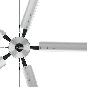
Hunter Industrial Trak Edge Commercial Fan: Electrical Contractor's Installation Guide

If you are specing, bidding, or installing the Hunter Industrial Trak Edge on a commercial job, this guide covers everything you need from pre-bid to post-install. Electrical specs, circuit sizing, junction box requirements, control wiring, multi-fan networking, sprinkler coordination, and code compliance are all here.
Is This Fan Right for Your Job?
Start here before anything else.
The Trak Edge is UL 507 Wet Rated. That is the stronger of the two outdoor ratings. It covers fully indoor spaces, covered outdoor areas such as open-air restaurants, patios, and pavilions, and semi-exposed commercial environments. You do not need to argue damp versus wet with an inspector on a covered patio job.
Ideal environments for the Trak Edge Fan:
- Commercial office spaces
- Retail and showrooms
- Restaurants and hospitality
- Fitness studios and wellness spaces
- Light commercial and mixed-use buildings
- Indoor covered outdoor and patio areas
The fan runs on single-phase AC, 120V or 240V. Most commercial buildings with three-phase panels also have single-phase circuits available, making installation straightforward in the majority of commercial environments.
Electrical Specifications
Everything you need for load calculations in one place. Fan motor and light kit are separate loads.
Motor Specs by Diameter
| Diameter | Max Power (W) | Max Amps at 120V | Max Amps at 240V | Hanging Weight |
|---|---|---|---|---|
| 5ft | 68W | 0.57A | 0.31A | 48 lbs |
| 6ft | 73W | 0.61A | 0.33A | 48.5 lbs |
| 7ft | 74W | 0.62A | 0.34A | 49 lbs |
| 8ft | 102W | 0.85A | 0.46A | 49.5 lbs |
Optional LED Light Kit (all diameters, sold separately)
| Spec | Value |
|---|---|
| Max Power | 30W |
| Max Current at 120V | 0.25A |
| Max Current at 240V | 0.13A |
| Color Temperature | 3,000K |
| Light Output | 2,600 lumens |
| Min Efficiency | 80 lm/W |
Worst-case combined load (8ft fan plus light kit at 120V): 1.10A
The DC motor keeps these numbers low. On a large multi-fan job, the savings across the panel add up fast.
Circuit Sizing
NEC 210.20(A) requires overcurrent protection sized at 125% of the continuous load.
Ceiling fans in commercial occupancies can be classified under Article 422 as appliances or under Article 430 as motors. Confirm with your AHJ before sizing overcurrent protection. The classification changes your calculation method.
Using the 80% continuous load limit on a standard 20A, 120V branch circuit gives you 16A of usable capacity. At worst-case draw of 1.10A per fan (8ft with light kit), that is approximately 14 fans per 20A circuit. Smaller diameters without the light kit draw well under 1A each.
Junction Box Requirements
All four Trak Edge diameters comes close to 50 lbs.
NEC 314.27(D) requires an outlet box listed and marked for fan support at the fan's actual weight.
Hunter's installation manual requires a box marked acceptable for fan support of 70 lbs. Do not use a standard fan box rated only to 35 lbs. Use a box rated and marked for 70 lbs at every location, or a fan-rated brace bar rated for the load if you are installing between joists.
This is a code item and a warranty item. An undersized box fails inspection and voids the manufacturer's warranty.

Location Planning and Clearances
These are Hunter's stated requirements from the installation manual. Get these confirmed before rough-in.
Minimum clearances:
- Bottom of blade to floor: 10 feet minimum
- Blade tip to nearest wall or obstruction: 30 inches minimum
- Fan to any light fixture: 2 feet minimum
- Fan to any air discharge (HVAC, evaporative cooler): distance of at least 2 times the fan diameter
Ceiling angle: The Trak Edge supports standard flat mounting and angled mounting. Maximum ceiling angle is 34 degrees. The fan cannot be mounted on a ceiling with an angle greater than 34 degrees.
Fan spacing for multi-fan jobs:
| Diameter | Min Spacing | Max Spacing |
|---|---|---|
| 5ft | 14ft | 20ft |
| 6ft | 16ft | 24ft |
| 7ft | 18ft | 28ft |
| 8ft | 20ft | 32ft |
Downrod Selection
The standard 11-inch downrod ships with every fan.
Optional downrod lengths available from Hunter:
- 23 inches
- 35 inches
- 47 inches
- 59 inches
The motor housing profile is 25.8 inches. Add your chosen downrod length and canopy depth to calculate where the blade plane will land. Confirm the 10-foot floor clearance before rough-in. Selecting the wrong downrod after the ceiling is closed costs time and money.
For ceiling heights above 14 feet, the 47-inch or 59-inch downrod keeps the blades in an effective airflow zone. Hunter recommends a minimum of 10 feet from the floor for best performance in most commercial spaces.
Every Trak Edge downrod comes standard pre-assembled and pre-wired. Mounting options are standard flat and angled, so the downrod works on both flat and vaulted ceiling installations without additional hardware.
Sprinkler Coordination
This section applies to any job with a fire sprinkler system. It is code and it is your responsibility as the installer.
NEC and NFPA 13 requirements for fan placement in sprinklered buildings:
- Fan must be located at least 3 feet below any sprinkler deflector
- Fan must be centered between 4 adjacent sprinklers
- Fan placement must not interfere with sprinkler operation
Review NFPA 13 before rough-in on any sprinklered job. Mark fan locations on the RCP and confirm spacing with the fire protection contractor before you anchor anything. Repositioning a fan location after rough-in because it conflicts with a sprinkler head is avoidable with a five-minute conversation early.
Control Options and Wiring
Every Trak Edge ships with a battery-powered RF remote. It controls speed, direction, and lighting. No wiring is required for basic single-fan operation.
When a wall controller is specified, the wiring is not line voltage. All three wall controllers run on Power over Ethernet (POE) via CAT5e cable. There is no line voltage at the wall controller location.
Every Trak Edge ships with an RF remote included at no additional cost. It handles speed, direction, and lighting for single-fan operation with no wiring required. The wall controllers below are optional upgrades for multi-fan control.
Wall Controller Options
| Controller | Fan Capacity | Power Source | Wiring | Key Features |
|---|---|---|---|---|
| Basic Wall Control (P/N 78240) | Up to 5 fans | POE | CAT5e | Speed, direction, lighting |
| 3" Touchscreen (P/N 74224) | Up to 10 fans | POE | CAT5e | Speed, direction, lighting, alerts |
| 4" Touchscreen (P/N 74225) | Up to 30 fans | POE | CAT5e | Full control, diagnostics, scheduling, zoning, naming |
Wall controllers mount to a standard single-gang junction box.
Three things to sort out before rough-in:
First, the fan itself is the POE power source. The wall controller is powered through the CAT5e cable, and the fan supplies that power directly. You do not need a separate POE switch or POE injector. The only switch required is the Modbus splitter, which is included with the wall controller kit when ordered through Hunter.
Second, on commercial jobs, low-voltage cabling is often pulled by a low-voltage sub or data contractor, not the EC. Clarify trade responsibility for the CAT5e run before rough-in. If you are responsible for it, bid it. If you are not, coordinate with the GC so nobody assumes the other trade covered it.
Third, if fans are operated by RF remote only with one remote per fan, no CAT5e wiring is needed between fans. However, if a wall controller is specified, CAT5e does run between fans in a daisy chain as part of the network. Your line voltage rough-in at each fan location remains independent regardless of which control method is used.
Dip Switch Configuration
This step is required on every networked installation. Missing it is the most common reason a multi-fan network does not work at startup.
Each fan has a red dip switch inside the motor housing. On a networked install, each fan must be assigned a unique number that corresponds to its position on the network (Fan 1 through Fan 31).
- Twist the upper motor housing counterclockwise to access the fan control board
- Locate the red dip switch
- Set the switch positions according to the dip switch table in the installation manual for that fan's assigned number
- Re-seat the upper motor housing and twist clockwise until the gap between the housing and fan is fully closed
Dip switch positions are read left to right across 5 positions. The table covers Fan 1 through Fan 31. Every fan on the network must have a unique dip switch setting. Two fans set to the same number will conflict.

Multi-Fan Network Wiring Topology
The network runs as a daisy chain, not individual home runs to the controller.
Each fan ships with one Modbus splitter and 50 feet of CAT5 cable.
Wiring sequence:
- CAT5 cable from Fan 1 connects to Modbus Splitter COM1 port on Fan 1
- CAT5 cable from Fan 1 Modbus Splitter COM2 port connects to Fan 2 Modbus Splitter COM1 port
- Continue the chain through all fans in the network
- The wall controller connects to COM3 of Fan 1, not to the last fan in the chain
Plan your conduit and cable routing for a daisy chain layout, not a star. Hunter provides 50 feet of CAT5 cable with each fan. Fans can run much longer distances than 50 feet between them using your own CAT5 cable. The included 50-foot cable is a starting point, not a hard limit.
Fire Relay Integration
On any commercial job with a fire alarm system, all fans must shut down on alarm activation. The Trak Edge supports this through a fire relay connection using the CAT5 cable.
Connect pins 3 (green-stripe) and 6 (green-solid) from the CAT5 to a normally open relay output on the fire panel. When the relay closes, all fans shut off.
Hunter sells a pre-made CAT5 Fire Relay Harness (P/N 78253) with pins 3 and 6 already exposed, which saves time on the termination. If you are going straight into the BMS rather than a standalone relay, also cut pins 4 (blue-solid) and 5 (blue-stripe).
Confirm fire relay requirements with the fire alarm contractor early. Do not leave this for final walkthrough.
LED Light Kit Activation
If the light kit is installed and a wall controller is used, the LED function must be manually activated in the controller settings after installation. It does not turn on automatically.
Activation steps using the 4" Touchscreen Controller:
- Select the menu icon
- Select Accessibility, then Admin Login
- Enter your 4-digit admin PIN
- Select the fan you want to activate the light on
- Go to Settings for that fan
- Scroll to Enable LED and toggle it on
- Repeat for each fan with a light kit installed
If you install the light kit and a contractor or client calls back saying the light does not work, this is the first thing to check before rolling a truck
Retention Cable
The retention cable must be installed on every fan. Failure to install it voids the warranty.
The retention cable wraps around the building structure rated to withstand double the installed fan weight and secures through the canopy mounting slot. Leave approximately 3 inches of slack at the top of the downrod opening. Secure with the provided cable clamps, orienting the U-bolt on the dead end and the clamp on the live end. Reversing the orientation crushes the wire and reduces its load rating.
Check the retention cable annually. Inspect for fraying on any visible portion. This is a safety system, not a formality.
Certifications and AHJ Acceptance
The Trak Edge is ETL/Intertek certified to ANSI/UL 507 and CSA C22.2 No. 60335-1 and 60335-2-80 in North America. It also carries the International Low Voltage Directive 2014/35/EU, IEC, and CE markings.
NEC 110.3(A)(1) requires equipment listed and labeled by a nationally recognized testing laboratory. ETL by Intertek is OSHA-recognized under the NRTL program, the same as UL. They are legally equivalent under the NEC and federal safety standards.
If an AHJ pushes back, ask them to cite the specific code section that disqualifies ETL-listed equipment. In most cases they cannot produce one. Hunter's technical team is available to provide documentation if you need it for a difficult AHJ. Call 1-844-591-3267 or email fansupport@hunterfan.com.
Warranty and Post-Install Support
The Trak Edge carries a 5-year warranty covering all components. Most commercial fan warranties exclude parts or limit coverage to the motor only. This one does not.
Document the installation. Record the fan diameter, voltage, serial number, and installation date at each location. If a warranty claim comes up inside 5 years, having that documentation speeds the process and protects your relationship with the owner.
Hunter Industrial has U.S.-based technical support. All fan controls are factory-configured and ready to use. Do not make changes to any part of the fan without consulting Hunter Industrial first, as unauthorized modifications void the warranty.
Purchase direct at industrialfans.hunterfan.com.
Ready to Spec the Trak Edge on Your Next Job?
All specs, technical downloads, submittal sheets, and ordering options are on the Hunter Industrial website. If you have questions before you buy, Hunter's U.S.-based technical team is available by phone or email.